Multi-digit 7-segment displays typically have two or more digits, each of which consists of a 7-segment display by itself. The common lines of each individual digit are used to select the digit to be lit. The driver program uses a technique called “multiplexing”, i.e. lighting one digit at a time very rapidly to display all the digits.
Typical Pin Out
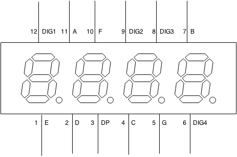
The figure below shows the typical pin-out (i.e. the layout of pins) on a typical 4-digit display. Notice the pins labeled “DIG1” through “DIG4” that are used to activate each digit. Also notice that there is no common LOW (for a common cathode display) or a common HIGH (for a common anode display), unlike that of a single-digit display.
Schematic
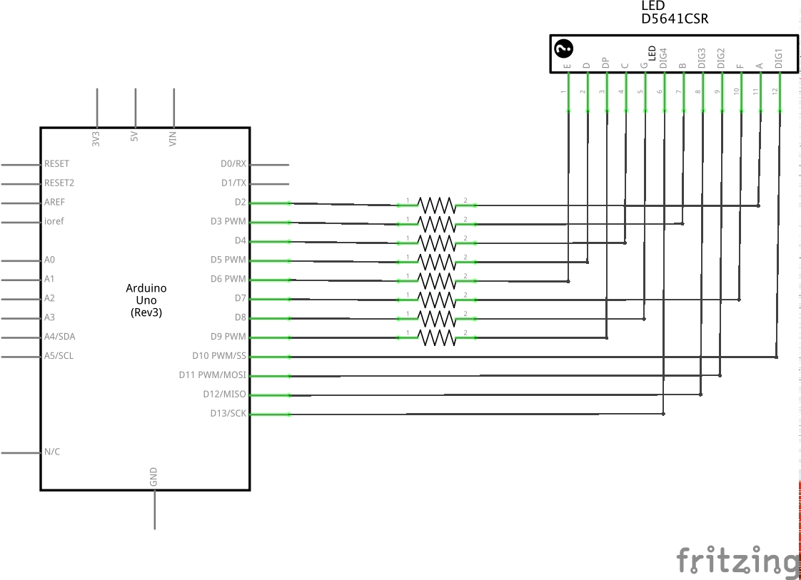
The schematic (also called “circuit schematic” or “circuit diagram”) shows how a typical 4-digit display is hooked up to an Arduino. Please note that in schematics, the way the pins are represented does NOT necessarily match the pinout of the device.
Circuit Schematic
The Code
Code can be downloaded from GitHub
 1 // the start of the pins used for A-G - must be sequential
 2 int segmentStart = 2;
 3
 4 // the start of the common pins - must be sequential
 5 int digitStart = 10;
 6
 7 // this code can use either polarity of display.
 8 // true if common is high when ON, otherwise false.
 9 boolean commonAnode = false;
10
11 // the number of digits your display has.
12 int numDigits = 4;
13
14 void setup() {
15   // Enable all A-G and DP and outputs,
16   // set them to OFF
17   for(int i=0;i<8;++i) {
18     pinMode(segmentStart + i, OUTPUT);
19     digitalWrite(segmentStart + i, commonAnode?1:0);
20   }
21
22   // Setup all the common pins, initially OFF.
23   for(int i=0;i<numDigits;++i) {
24     pinMode(digitStart + i, OUTPUT);
25     digitalWrite(digitStart + i, commonAnode?0:1);
26   }
27 }
28
29 void loop() {
30   // display a number on the 4-digit display.
31   int amount = 1234;
32
33   for(int i=(numDigits-1);i>=0;--i) {
34     // find the current digit, which is in the low 4 bits
35     int digit = amount % 10;
36
37     writeDigitToDisplay(digit);
38
39     // enable the right digit for display
40     digitalWrite(digitStart + i, commonAnode?1:0);
41
42     // short delay between changes.
43     delay(1);
44     // Turn of the digit
45     digitalWrite(digitStart + i, commonAnode?0:1);
46
47     // get the next digit.
48     amount = amount / 10;
49
50     //rinse, and repeat
51   }
52 }
53
54 // Now we define the bits that are on and off
55 // for each segment, These are used in the
56 // function below to turn the correct segments on.
57 int dig[16] = {
58 // bits     6543210
59 // digits   abcdefg
60           0b1111110,//0
61           0b0110000,//1
62           0b1101101,//2
63           0b1111001,//3
64           0b0110011,//4
65           0b1011011,//5
66           0b1011111,//6
67           0b1110000,//7
68           0b1111111,//8
69           0b1111011,//9
70           0b1110111,//a
71           0b0011111,//b
72           0b1001110,//c
73           0b0111101,//d
74           0b1001111,//e
75           0b1000111 //f
76 };
77
78 void writeDigitToDisplay(int digit) {
79   digit = (digit & 0x0f);
80   // iterate through each bit
81   for(int i=0;i<7;++i) {
82     // isolate the current bit in the loop.
83     int currentBit = (1<<(6-i));
84
85     // check if the bit is on, and invert for
86     // commonhigh if needed.
87     int bitOn = (currentBit&dig[digit])!=0;
88     if(commonAnode) {
89       bitOn = !bitOn;
90     }
91
92     // and lastly set the bit
93     digitalWrite(segmentStart+i, bitOn);
94   }
95 }