Motors, and motor drives are, perhaps, the most fun aspects of electronics. The very thought of converting electrical pulses into mechanical energy is amazing to the human mind. Motors power a wide variety of physical objects in our world - from cell phone buzzers to robots to electric cars.
Lesson Outline
In this lesson we will
- Examine how the following three types of motors work:
- DC motors
- Stepper motors
- Servo motors
-
Identify appropriate methods to drive these motors from an Arduino.
- Write programs to control these motors using their drive circuits, and available Arduino libraries.
DC Motors
DC motors are perhaps the simplest motors to understand. A current flows through a coil that is placed within a magnetic field that is generated by permanent magnets. The interaction between the electromagnetic field (generated when the current flows through the coil) and the magnetic field from the permanent magnets results in a perpendicular force being generated on the coil (look at Fleming’s Left Hand Rule) for more details.
The figure below (from Wikimedia Commons) shows the internal structure of a typical DC motor.
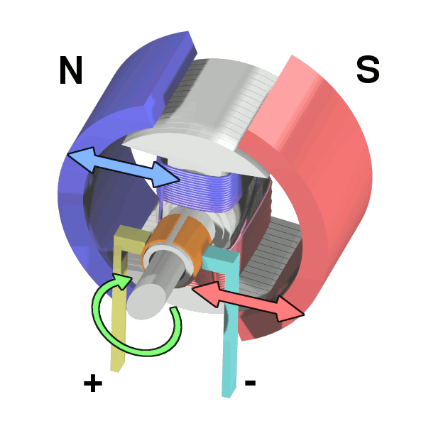
The speed at which a DC motor rotates is directly proportional to the voltage that is applied across it. The direction in which the motor rotates (clockwise or anticlockwise) is determined by the polarity of the voltage applied across the motor - reverse the polarity and the motor will reverse its rotation.
Controlling Motor Speed: PWM
As we said above, the speed of the motor is controlled by the voltage that is applied across its terminals. Apply a lower voltage, and the speed is lower than that obtained by applying a higher voltage.
One technique for controlling the analog voltage through the use of digital signals is called Pulse Width Modulation (PWM). PWM signals vary the ratio of the time that a signal is switched on to the time that the signal is switched off when generating signals with a constant frequency. This ratio is called the duty cycle.
For an illustration, look at the following figure (from the Arduino web site).
The figure shows a typical set of PWM waveforms with varying duty cycles. Note that the frequency of the waveforms is the same in every row of the illustration. However, the length of time (and, hence, the width) that the pulse stays on varies depending on the argument to the analogWrite function. With a 50% duty cycle (analogWrite(127)) the pulse stays on for half the time period of the wave. Due to the inherent inertia of the electrical system that is being controlled (e.g. a motor) the system perceives the voltage of a 50% PWM signal to be half of the supply voltage.
For PWM to work, the switching frequency must be significantly higher than that perceived by the load. Typical switching frequencies for DC motors are in the one to ten kilohertz range. Unfortunately, the PWM output on the Arduino Uno runs at either 490 Hz or 980 Hz (pins 5 and 6 only), but it seems to suffice for most hobby projects. Note that this is not so much a limitation of the ATMega hardware, as it is a limitation of the Arduino firmware.
Controlling Motor Direction: H-Bridge
There are a number of ways of controlling the direction of rotation of a DC motor, but the most common is the “H-bridge”, named after the H-shaped layout of switches in the circuit. The figure below (from Wikimedia Commons) shows the notional representation of an H-bridge circuit for controlling a DC motor.

So, how does this circuit work?
To rotate the motor in one direction (let’s call it the “forward” direction) switches S1 and S4 are closed. Current flows through the motor from the top-left, to the bottom-right. The current flow in the motor is from its left terminal to its right.
To rotate the motor in the opposite direction (let’s call it the “reverse” direction) switches S1 and S4 are opened, and switches S3 and S2 are closed. Current flows from the top-right to the bottom-left, and within the motor it flows from the right to the left, thereby reversing its direction.
To let the motor “coast” to a stop, open all the switches. This removes all sources of electricity from reaching the motor, and lets it gradually come to a stop. If you want to brake (or rapidly stop) the motor, you do that by creating a short circuit between the two terminals of the motor. This is accomplished by closing S2 and S4, and leaving S1 and S3 open.
Here is a basic truth table for the H-Bridge circuit:
| S1 | S2 | S3 | S4 | Output |
|---|---|---|---|---|
| 1 | 0 | 0 | 1 | Forward |
| 0 | 1 | 1 | 0 | Reverse |
| 0 | 1 | 0 | 1 | Brake |
| 0 | 0 | 0 | 0 | Coast |
Flyback Diodes
When using H-bridges (or any other switching circuit) to handle inductive loads (such as motors, solenoids, relays, etc.)